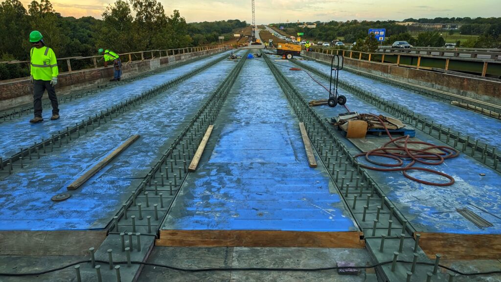
In highway bridge design and structural detailing, confusing Layout Length with Span Length is one of the most common early-stage drafting and modeling mistakes. While layout length governs roadway stationing, bridge coordinates, and substructure placement, span length governs structural mechanics, live load distribution, and moment/shear demands.
This guide explains the fundamental distinction between layout length and span length under the Missouri Department of Transportation (MoDOT) Engineering Policy Guide (EPG 751) and AASHTO LRFD Bridge Design Specifications.
What is Layout Length in Bridge Design?
Layout Length is the horizontal dimension measured along the roadway reference line (station line or profile grade line) between established working points of the bridge—typically between the centerline of end bents (abutments) or backwall-to-backwall limits.
Key characteristics of Layout Length include:
- Alignment Dependent: Measured along the stationing of the highway alignment, accounting for horizontal curves, spirals, and tangents.
- Substructure Positioning: Used by roadway engineers, surveyors, and contractors to stake out bridge bents, abutments, and wingwalls in project coordinates.
- Skew Influence: On skewed bridges, layout length measured along the roadway station line differs from the normal distance between substructure units by the cosine of the skew angle (\(L_{ ext{normal}} = L_{ ext{station}} \cdot \cos heta\)).
What is Span Length in Structural Analysis?
Span Length (often termed effective span length or design span) is the direct center-to-center distance between the structural bearings supporting a girder, slab, or beam unit.
In AASHTO LRFD Bridge Design, span length is the governing parameter for:
- Bending Moment & Shear Demands: Maximum dead load and live load moment calculations (such as simple-span maximum moment \(M = rac{w L^2}{8}\)).
- Live Load Distribution Factors (LLDF): AASHTO LRFD Table 4.6.2.2 distribution factor equations depend directly on the structural span length \(S\) and girder spacing \(L\).
- Deflection & Camber Limits: Elastic deflection checks under HL-93 live loading and long-term camber predictions for prestressed concrete girders.
MoDOT Engineering Policy Guide (EPG 751) Standards
Under MoDOT EPG Section 751 (Bridge Design Guidelines), detailing standards explicitly separate the roadway alignment layout from girder framing plans:
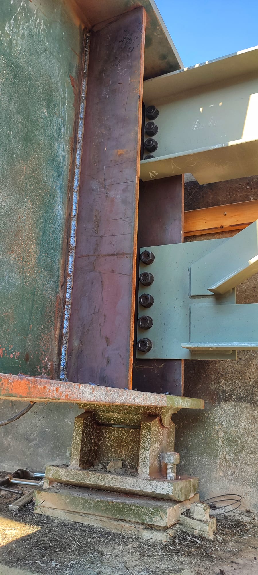
- Bearing Setbacks: The centerline of bearing on a pier cap or end bent is offset from the centerline of the bent by a designated setback distance (typically 10 to 18 inches depending on girder size, bearing pad dimension, and expansion joint details).
- Girder Fabrication Length: The total physical length of a prestressed concrete girder (end-to-end) is longer than the design span length, extending past the centerline of bearings into the end diaphragm or expansion gap.
- Thermal Movement & Expansion Gaps: Expansion joint calculations at bents must account for thermal expansion, shrinkage, and creep over the entire continuous superstructure layout length.
Prestressed Concrete Girder Design (NU Girders & I-Girders)
For prestressed concrete bridges—such as Missouri standard NU girders (NU35, NU43, NU53, NU63, NU70) and AASHTO I-girders—designers must account for three distinct length dimensions:
- Design Span Length (\(L_{ ext{span}}\)): Centerline of bearing to centerline of bearing. Used in PGSuper, Bentley OpenBridge Designer, and hand calculations for AASHTO LRFD flexural and shear design.
- Fabrication Length (\(L_{ ext{girder}}\)): Physical overall length of the precast beam delivered from the precast yard, including bearing overhangs and end bevels for grade slopes.
- Substructure Layout Length (\(L_{ ext{layout}}\)): Station-to-station distance between substructure working lines on the bridge layout sheet.
Summary Comparison: Layout vs. Span vs. Fabrication Length
| Dimension Type | Reference Points | Primary Application | Governing Standard |
|---|---|---|---|
| Layout Length | Centerline of bents / Roadway station working points | Roadway geometry, coordinates, and substructure staking | MoDOT EPG 751.10 & Roadway Plans |
| Span Length | Centerline of bearing to centerline of bearing | AASHTO LRFD moment, shear, and live load distribution | AASHTO LRFD Chapter 4 & 5 |
| Girder Length | Physical end-to-end of precast or steel member | Fabrication, shop drawings, shipping, and bearing seat clearance | MoDOT EPG 751.20 & Precast Standards |
Practical Design Checklist for Bridge Engineers
- Always verify whether the geometric layout uses stationing along the centerline of road or the baseline of construction.
- Double-check bearing setback dimensions on bent caps to ensure structural span lengths in analysis software (e.g., AASHTOWare BrR, PGSuper, OpenBridge) match physical bearing locations.
- On skewed bridges, verify that girder spacing and individual span lengths are calculated along each girder line rather than assuming uniform station differences.
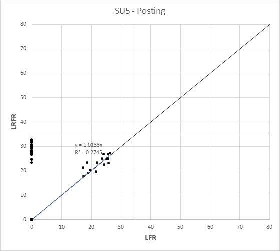
- For related research on Missouri bridge capacity evaluation, read the Comparative Study of LRFR and LFR Rating for Missouri Bridges.

Discussion
0 comments